Critical updates
Please review the following critical hardware, software, and commissioning updates before starting an Enphase Energy System installation.
Download the newest troubleshooting guide to resolve issues with the IQ Battery 5P, IQ System Controller 3/3G, and Communications Kit 2.
Durante la instalación del cable de control de Enphase para el IQ System Controller 3/3G y/o IQ Battery 5P, las instrucciones anteriores aconsejaban cortar el cable rojo no utilizado. Con los nuevos productos en desarrollo establecidos para utilizar este cable, hemos actualizado las directrices de instalación para recomendar la conexión del cable rojo en todo el sistema.
Para obtener más información, consulte las directrices de instalación actualizadas que se proporcionan con las guías de instalación rápida del IQ System Controller y IQ Battery 5P.
During the installation of the Enphase Control Cable for the IQ System Controller 3/3G and/or IQ Battery 5P, previous instructions advised cutting the unused red wire. With new products in development set to utilize this wire, we have updated the installation guidelines to recommend connecting the red wire throughout the system.
For more information, refer to the updated installation guidelines provided with the quick install guides of the IQ System Controller and the IQ Battery 5P.
If an IQ System Controller stops reporting to IQ Gateway after commissioning, watch this video to learn some of the basic troubleshooting steps. To know how to power cycle and reprovision the IQ System Controller, see the steps in this video.
Si un IQ System Controller deja de informar a el IQ Gateway después de la puesta en marcha, vea este vídeo para aprender algunos de los pasos básicos para la solución de problemas. Para saber cómo realizar un ciclo de alimentación y volver a aprovisionar el IQ System Controller, consulte los pasos de este vídeo.
Para mejorar la experiencia del propietario y minimizar los problemas causados por errores en el cableado del contador, los instaladores ya no podrán utilizar la opción Omitir el asistente del contador para ningún sistema solar o de almacenamiento. Los pasos del Asistente del Medidor y la Validación funcional serán obligatorios para completar la puesta en servicio de un sistema.
En un cambio relacionado con los sistemas de almacenamiento o respaldo de tercera generación (IQ Battery 5P o IQ System Controller 3), los instaladores no podrán generar un informe de resumen a menos que se complete el paso de Validación funcional.
To enhance the homeowner's experience and minimize truck rolls caused by meter wiring errors, installers will no longer be able to utilize the Skip the meter wizard option for any solar or storage system. The Meter Wizard and Functional Validation steps will both be mandatory to complete commissioning of a system.
In a related change for 3rd-generation storage or backup systems (IQ Battery 5P or IQ System Controller 3), installers will not be able to generate a summary report unless the Functional Validation step is completed.
Para garantizar que los datos proporcionados son precisos, hemos puesto en marcha una iniciativa para solucionar los problemas de los medidores en toda nuestra flota. Para cualquier ubicación que tenga medidores de consumo habilitados (pero no instalados físicamente en el sitio) y no esté rastreando ninguna información de consumo real, esos medidores se deshabilitarán automáticamente, lo que hará que el consumo deje de aparecer en la aplicación Enphase. Consulte https://support.enphase.com/s/article/Why-does-system-consumption-mirror-system-production para obtener más información.
Atención instaladores :
Estamos emitiendo una actualización crítica con respecto al cableado del System Shutdown Switch (SSD)al IQ System Controller. Esto es esencial para garantizar el correcto funcionamiento y la seguridad del equipo.
Directrices clave para la instalación:
No Co-Location: El cableado SSD no debe estar en el mismo conducto que los conductores de alimentación de CA. Esto es crucial para evitar interferencias y mantener la integridad del sistema.
Separación obligatoria: Garantice una separación mínima de 2 pulgadas entre el conducto de cableado SSD y el conducto de cableado de red/carga/ Distributed Energy Resource (DER).
Colocación específica del conducto: El conducto de cableado SSD debe colocarse en la parte inferior, izquierda o derecha de la caja, estrictamente dentro de la región de perforación de conductos especificada.
Consulte la imagen siguiente, que ilustra las directrices antes expuestas.
El cumplimiento de estas directrices es fundamental para el funcionamiento fiable del IQ System Controller y para la prevención de riesgos eléctricos. Su incumplimiento puede provocar problemas de rendimiento del sistema y comprometer la seguridad.
Visite nuestra página web sobre el nuevo microinversor IQ8 para aplicación comercial trifásica y así poder conocer todo al respecto.
El nuevo microinversor IQ8X se integra perfectamente con módulos de 80 semicélulas, 88 semicélulas y 96 células con alta tensión de circuito abierto (Voc inferior a 80 V) a las temperaturas más bajas. Para obtener una visión completa de sus capacidades, consulte la hoja de datos del microinversor IQ8X disponible.
No colocar en paralelo ni empalmar conductores de batería en las terminales IQ Battery 3T o 10T. No utilizar conectores de conexión múltiple ni conectores para conductores dentro del compartimiento de cableado de IQ Battery 3T/10T. Empalmar conductores en las terminales de la batería o utilizar conectores de conexión múltiple/conectores para conductores dentro de los compartimentos de conductores puede provocar daños al equipo y supone un posible riesgo de incendio. La guía de instalación rápida (QIG) para IQ Battery 3T/10T, disponible aquí, se actualiza con instrucciones de cableado para conectar las baterías en paralelo. También puede consultar nuestro video de capacitación disponible aquí para conocer las mejores prácticas al cablear IQ Battery 3T y 10T.
Transforme la forma en que aprovecha y utiliza su energía solar con nuestra nueva línea de microinversores de alta corriente continua de la serie IQ8, los IQ8MC, IQ8AC e IQ8HC. Vea el vídeo para conocer sus características, compatibilidad y mucho más.
El IQ Gateway está dentro del IQ Combiner y muestra el error "El Gateway no responde" en la aplicación Enphase cuando está desconectado de Internet y de la nube Enphase. Para solucionar este error, vuelve a conectar tu IQ Combiner a la nube Enphase.
Una vez conectado, espera a que el indicador LED junto al icono de la nube en el IQ Gateway se vuelva verde fijo para confirmar que la conexión se ha realizado correctamente.
La representación de la conexión del cable conductor del TC de consumo (L1, L2) a los puertos de medición de IQ Gateway representada en la etiqueta de cableado y en la Guía de instalación rápida (QIG) para IQ Combiner 4/4C e IQ Combiner 5/5C era incorrecta en algunas versiones de producción. Este problema se ha rectificado en todas las unidades fabricadas a partir de ahora, donde la representación correcta del código de colores se proporciona ahora en las etiquetas y QIGs.
SKUs afectados.
X2-IQ-AM1-240-4
X2-IQ-AM1-240-4C
X-IQ-AM1-240-5
X-IQ-AM1-240-5C
¿Cómo identificar si un IQ Combiner 4/4C o IQ Combiner 5/5C se ha enviado con la etiqueta incorrecta?
Para identificar si un IQ Combiner 4/4C o IQ Combiner 5/5C se ha enviado con la etiqueta incorrecta, compruebe la etiqueta de cableado (situada en la puerta interior) de su IQ Combiner. Si coincide con la representación de la Figura A para el IQ Combiner 4/4C o la Figura B para el IQ Combiner 5/5C, su unidad tiene la etiqueta de cableado incorrecta.
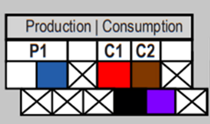
Figura A: Etiqueta de cableado incorrecto (IQ Combiner 4/4C))
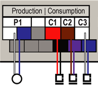
Figura B: Etiqueta de cableado incorrecto (IQ Combiner 5/5C)
La etiqueta de cableado actualizada y correcta se muestra en la Figura C para el IQ Combiner 4/4C y en la Figura D para el IQ Combiner 5/5C.
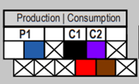
Figura C: Etiqueta de cableado correcto (IQ Combiner 4/4C)
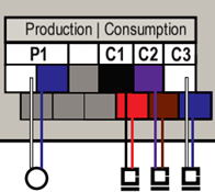
Figura D: Etiqueta de cableado correcto (IQ Combiner 5/5C)
¿Cómo se accede a la Guía de instalación rápida corregida?
La Guía de instalación rápida (QIG) corregida del IQ Combiner 4/4C y la Guía de instalación rápida (QIG) del IQ Combiner 5/5C ya están disponibles en el centro de documentación. Por favor, siga las instrucciones proporcionadas en esta guía de instalación para asegurar la correcta instalación de los TC.
¿Cuáles son las medidas correctivas si ya se han instalado incorrectamente?
Si los TC se instalaron incorrectamente, la polaridad de las lecturas se invierte. Por lo general, la aplicación Enphase Installer App lo identifica y marca durante la puesta en servicio. Sin embargo, si se produce una instalación incorrecta, puede rectificarse incluso después de abandonar el emplazamiento mediante la opción "Invertir polaridad" disponible en el Enphase Installer Portal.
En este vídeo para instaladores, el equipo de Enphase le ofrece un rápido recorrido por el Sistema de energía Enphase de 3ª generación, que incluye la Batería IQ 5P, el Controlador de sistema IQ 3/3G, el Combinador IQ 5/5C, y el control y las comunicaciones por cable que ofrecen mayor fiabilidad, velocidad y rendimiento.
Accede al centro de recursos para diversas guías explicativas y de resolución de problemas sobre problemas discutidos con frecuencia:
Cómo actualizar la información del propietario mediante la aplicación Enphase Installer App
Cómo cambiar el perfil de red de un sistema utilizando la aplicación Enphase Installer
Cómo ejecutar un informe de perfil de red utilizando el Portal del Instalador de Enphase
Cómo cambiar la polaridad del TC utilizando el Portal del Instalador de Enphase
Enphase Service Manager: Gestión de RMA y solicitudes de reembolso de mano de obra con el Enphase
Almacenamiento de Energía Enphase: Cómo cablear el IQ Gateway
En el nuevo informe técnico de instalación de TC podrá ver cómo funcionan los TC, los tipos de TC compatibles con Enphase, procedimientos de instalación recomendados y otros detalles importantes. Y si surgen problemas con los TC en sus sistemas, este video le enseñará cómo solucionarlos con la Enphase Installer App.
Para garantizar una experiencia sin problemas en la puesta en marcha de equipos Enphase Energy System de 3ª generación utilizando la aplicación Enphase Installer, recomendamos encarecidamente ver este vídeo de resumen y asegurarse de que está utilizando equipos compatibles.
Tenga en cuenta que una batería IQ Battery 5P debe instalarse con un IQ System Controller 3/3G, y no puede instalarse con un IQ System Controller o IQ System Controller 2.
Una batería IQ 5P debe instalarse con un IQ Combiner 5/5C hasta que el Communications Kit 2 esté disponible. Se espera que los pedidos del Communications Kit 2 comiencen en agosto.
Descargue la nueva Guía del Enphase Service Manager para obtener información sobre cómo acceder y utilizar las funciones disponibles en la vista móvil y de escritorio del Enphase Service Manager.
Nuestro nuevo panel de control de gestión de flotas ayuda a nuestros socios instaladores y propietarios de activos a gestionar sus flotas de manera conveniente y realizar un seguimiento de su rendimiento. Puede referirse a esta guía para obtener más información e instrucciones. Observe este video para aprender más sobre el panel de control de gestión de flotas.
Descargue la nueva Guía del Portal del instalador de Enphase para aprender a acceder y utilizar las funciones disponibles en la vista móvil y de escritorio del Portal del instalador de Enphase.
Cuando se necesita el aprovisionamiento de microinversores y no hay nadie en el sitio para hacerlo, siempre se pueden agregar de forma remota mediante el Portal de instalación de Enphase, siempre que la puerta de enlace esté en línea y el microinversor esté conectado correctamente. Consulte este artículo para obtener más ayuda instrucciones detalladas.
Descargue el nuevo Manual de Resolución de Problemas de Instalaciones Solares para resolver problemas comunes del IQ Gateway y del monitoreo del consumo, incluida la detección y solución de ruido en la línea eléctrica, la conectividad del IQ Gateway, la configuración del TC y la polaridad inversa.
Activación y desactivación de un TC de consumo o producción:
Inicie sesión en Enphase Installer Portal y navegue hasta "Dispositivos" > "Medidor de consumo" o "Medidor de producción", seleccione el medidor de la lista en la pestaña "Dispositivos" y haga clic en "Activar" o "Desactivar" en la parte inferior del panel izquierdo.
Modificación de la configuración de un TC de consumo:
Inicie sesión en el Enphase Installer Portal y navegue a "Dispositivos" > "Medidor de consumo", seleccione el medidor en la pestaña "Dispositivos", haga clic en la opción deseada en el panel izquierdo, debajo de "Seleccionar ubicación del transformador de corriente de consumo", y haga clic en "Cambio de configuración".
Inversión de la polaridad de un TC de consumo o producción:
Cuando esté conectado localmente a un IQ Gateway, puede invertir la polaridad del TC utilizando el asistente de medidor de la Enphase Installer App. Puede encontrar más detalles en las notas de la versión de la Enphase Installer App (3.27.1). El IQ Gateway debe ejecutar la versión de software 7.0.104 o superior.
Si su empresa utiliza subcontratistas que necesitan acceso al Enphase Installer Portal para realizar su trabajo, ahora puede agregar sus cuentas existentes de Enlighten a sitios específicos de su flota con acceso limitado. Consulte la sección "Subcontratista autorizado" en las notas de la versión 22.2.0 para obtener instrucciones detalladas.
Los instaladores ahora pueden asegurarse de que los propietarios tengan acceso ininterrumpido a su Enphase App. Edite rápidamente los datos del propietario en la Enphase Cloud mediante el Enphase Installer Portal y la Enphase Installer App.
Con el Enphase Installer Portal actualizado, puede enviar un correo electrónico de acceso al sitio a sus clientes en unos simples pasos. Esto le ayudará a reducir el tiempo necesario para que sus clientes pongan en marcha y disfruten de su nuevo Enphase Energy System. Aprenda a reenviar el acceso a Enphase a un cliente utilizando el Enphase Installer Portal y la Enphase Installer App.
Descargue el nuevo manual de resolución de problemas de instalaciones solares para remediar complicaciones comunes de la IQ Gateway y el monitoreo de consumo, incluida la detección y resolución de ruido en la línea eléctrica, la conectividad de la IQ Gateway, la configuración del TC y la polaridad inversa.
Con el Enphase Installer Portal actualizado, puede enviar un correo electrónico de acceso al sitio a sus clientes con unos sencillos pasos. Esto le ayudará a reducir el tiempo necesario para que sus clientes puedan poner en marcha, supervisar y disfrutar su nuevo Enphase Energy System. Aprenda cómo reenviar el acceso a Enphase a un cliente.
En algunos casos, los medidores de producción y consumo se invierten inadvertidamente en la puesta en servicio. Aprenda a invertir la polaridad remotamente desde el Enphase Installer Portal.
Ahora puede emitir estas tareas de forma remota:
Aprovisionar varios dispositivos
Forzar actualizaciones de software
Reiniciar IQ Gateways • Comprobar tarifas
Reiniciar dispositivos IQ Battery
También puede realizar muchas más tareas con la nueva herramienta de Diagnóstico del Sistema. Haga clic aquí para obtener más información.
Esta norma no es retroactiva, y los sitios actuales no necesitan hacer ningún cambio.
Estos productos Enphase han sido certificados por UL Solutions según UL 1741-SB, 3ª edición para demostrar el cumplimiento con IEEE 1547:2018: IQ7, IQ8, IQ Battery 3/10/3T/10T e IQ System Controller 1/2. Las fichas técnicas correspondientes se han actualizado.
Se necesitan nuevos SKU para IQ Combiner 4/4C (X2-IQ-AM1-240-4, X2-IQ-AM1-240-4C) o IQ Gateway (ENV2-IQ-AM1-240) para la conformidad con IEEE 1547:2018. Consulte la tabla siguiente. Confirme con su distribuidor cuál SKU está previsto que reciba.
Sistemas con solo interconexión a la red y la mayoría de los sitios IQ Battery se pondrán en servicio como de costumbre con la aplicación Enphase Installer App (anteriormente Installer Toolkit). Para los sitios de IQ Battery con un extensor de rango Zigbee, por favor póngase en contacto con Soporte al Cliente para actualizar el software de la IQ Gateway antes de configurar el sistema. Este es un paso temporal y a partir de mediados de enero esta actualización se realizará en la Enphase Installer App (versión 3.28) sin necesidad de ponerse en contacto con Soporte al Cliente.
| Producto | SKU Existente | Nuevo SKU (IEEE 1547:2018 |
|---|---|---|
| IQ Combiner 4/4C | X-IQ-AM1-240-4 or X-IQ-AM1-240-4C |
X2-IQ-AM1-240-4 or X2-IQ-AM1-240-4C |
| IQ Gateway | ENV-IQ-AM1-240 | ENV2-IQ-AM1-240 |
Visite la página explicativa de IEEE 1547:2018 para más información.
Encontrará disponibles las fichas técnicas en el centro de documentación.
Seleccione las cargas de respaldo de modo que el consumo de energía de carga pico no supere el 30% de la potencia nominal de CA del sistema solar.
Utilice siempre uno o dos IQ Load Controllers y conéctelos correctamente al panel de cargas esenciales y al IQ System Controller 2.
Configure los contactos auxiliares (AUX) en el IQ System Controller 2 mediante la Enphase Installer App. Si no lo hace, el sistema de energía de respaldo de luz solar no funcionará correctamente.
Consulte el video de soporte y el resumen técnico para obtener más detalles.
A medida que veamos más módulos entrando en el mercado con corrientes continuas más altas, nuestra última actualización de firmware estará lista para soportar el aumento hasta 12 A. Leer las notas de la versión.
Esta versión está disponible para instalaciones en curso de Enphase Energy System que utilizan la última versión de la Enphase Installer App y como una actualización inalámbrica para sistemas ya instalados. Lea las notas de la versión completas para obtener más información.
Obtenga más información sobre los pasos para completar una actualización de software:
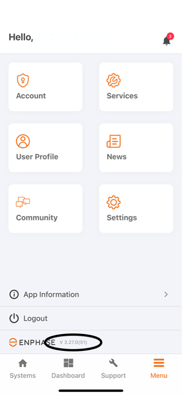
Antes de ir al sitio de instalación, abra la aplicación de instalación de Enphase y confirme que está ejecutando la versión 3.27.0. De lo contrario, descargue la última actualización de Apple App Store o Google Play Store.
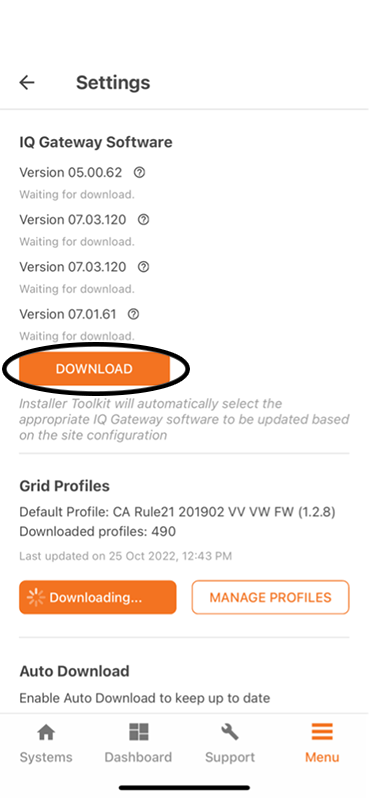
En la configuración de la aplicación de instalación, compruebe si el IQ Gateway ya ha descargado automáticamente la versión 7.03.120. Si no, pulse "Descargar". Recomendamos realizar este paso en la oficina a través de Wi-Fi antes de ir al campo.
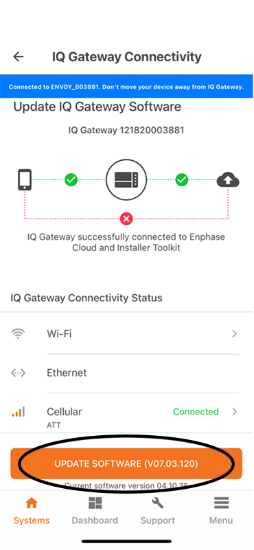
Una vez que llegue al lugar, conéctese al IQ Gateway y pulse "Update software (v07.03.120)".
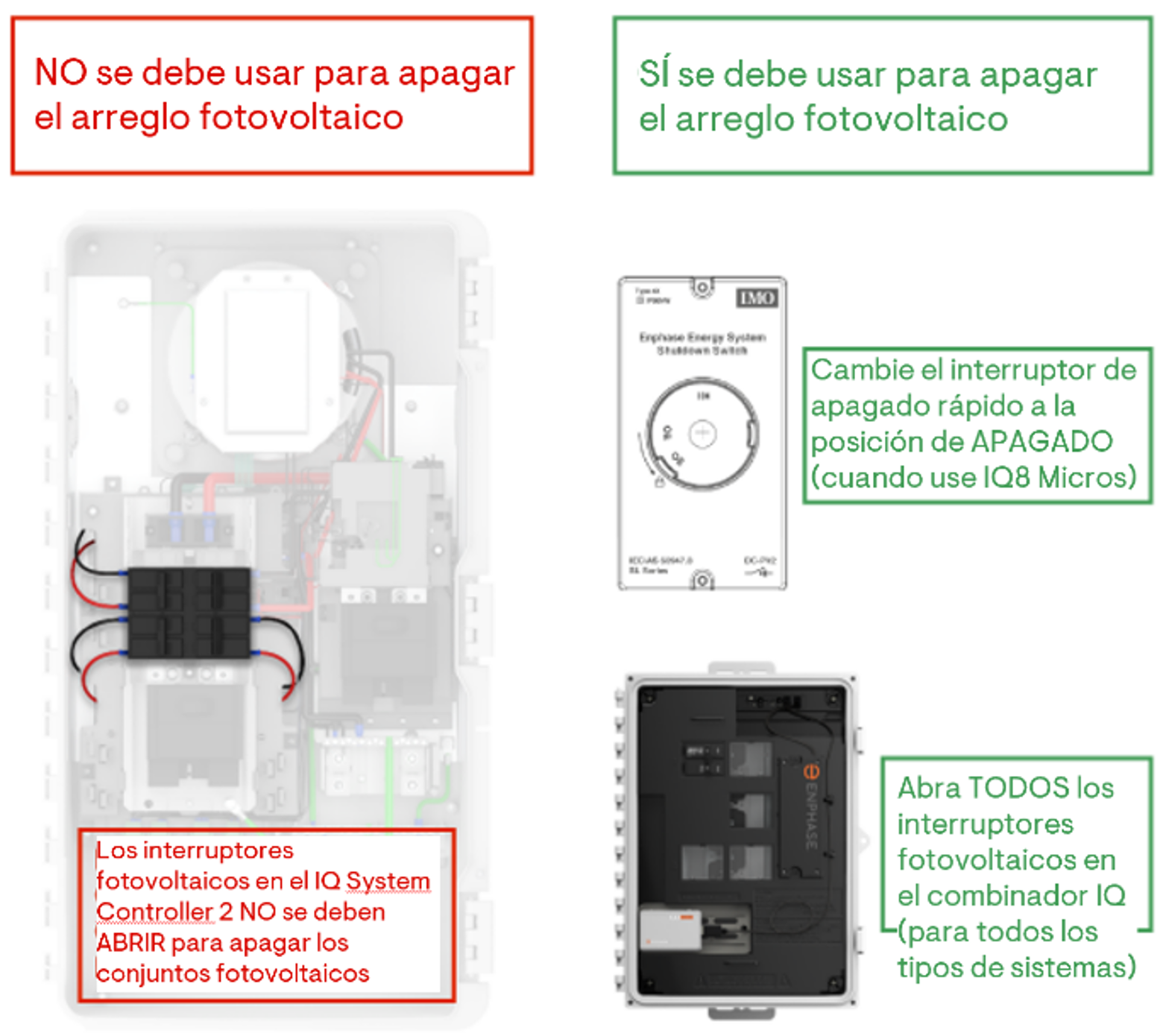
Durante la puesta en marcha o mantenimiento, NO utilice el interruptor fotovoltaico del IQ System Controller 2 para desconectar el sistema fotovoltaico. En su lugar, utilice el interruptor de apagado rápido, si está instalado, o bien los interruptores situados en la caja del IQ Combiner para desconectar los arreglos fotovoltaicos individuales.
La apertura del breaker fotovoltaico dentro del IQ System Controller 2 conducirá a un estado de desconexión persistente, y el IQ System Controller nunca volverá a conectar el relevador fotovoltaico. Esto es de diseño para proteger los electrodomésticos y las cargas de la casa de daños en caso de un fallo del interruptor.
Si un interruptor fotovoltaico se dispara debido a un evento de sobrecorriente, se aconseja a los instaladores que rectifiquen el fallo, cierren los breakers y llamen al servicio de atención al cliente de Enphase para eliminar el estado de error.
Esto es aplicable únicamente a las instalaciones del IQ System Controller 2.
El problema identificado se ha resuelto en nuestras fábricas y se limita a un lote específico de unidades. Durante la puesta en marcha, si se encuentra con un System Controller 2 que no se pueda provisionar y cuya señal BLE no sea visible durante un escaneo de Bluetooth del dispositivo móvil, póngase en contacto inmediatamente con su Gerente Regional de Ventas (RSM) o con el Servicio de Servicio al Cliente de Enphase (pulse 2-2-2 para dirigir rápidamente su llamada a la persona de apoyo adecuada). Haremos los arreglos para que nuestro equipo de servicio de campo visite el lugar y reemplace la tarjeta E3 dentro del System Controller 2. Nuestro equipo de Servicio al Cliente está disponible las 24 horas del día, los 7 días de la semana, solo marcando el número 707-774-7020 (877-797-4743 para inglés).
Para asegurar la correcta propagación del perfil de red y la capacidad de desactivar la producción de energía en Gateway IQ, (1) Actualice a la última versión de la aplicación de instalación y (2) Actualice el software de Gateway IQ al menos a la versión 7.00.92 a través de la aplicación de instalación de Enphase antes de aprovisionar los dispositivos. La actualización del software puede tardar hasta 15-20 minutos.
El actual SKU EP200G101-M240US01 de IQ System Controller 2 se suspende y se sustituye por el SKU EP200G-SC2-RSD-KIT. El nuevo SKU incluirá:
El breaker estará preinstalado en la ranura del generador en el IQ System Controller 2. Para obtener información adicional, consulte el documento de Mejores Prácticas.
Antes de la puesta en marcha, el DC Switch de la IQ Battery no debe encenderse, a menos que lo indique la Enphase Installer App. Encender el interruptor de CC antes de que se le indique puede dañar la batería IQ. Después de la puesta en marcha, siga siempre la secuencia para suministrar primero la alimentación de CA y luego encender el interruptor de CC. La secuencia de apagado de la alimentación de CA o del interruptor de CC es indiferente.
Si se deja el interruptor de CC encendido, sin alimentación de CA ni comunicación con el Gateway IQ, la batería se agotará. No seguir estas instrucciones puede dañar las celdas de la batería y anular la garantía limitada.
Haga clic aquí para saber cómo inspeccionar visualmente un breaker antes de la instalación.
Para evitar esta situación, actualice el software de Gateway IQ desde la aplicación de instalación de Enphase a una versión superior a la 7.
No cablee el interruptor de parada rápida mientras el controlador del sistema IQ 2 esté energizado/encendido. La instalación y el cableado del Interruptor de Parada Rápida deben tratarse como una instalación de cables vivos. Desenergice el sistema cuando desconecte o conecte cualquier cableado del RSD. Para obtener información adicional, consulte las mejores prácticas y el vídeo de demostración.
To ensure data being provided is accurate, we have started an initiative to clean up the meter issues across our fleet. For any location that has Consumption Meters enabled (but not physically installed on site) and is not tracking any actual consumption information, those meters will be automatically disabled which will cause the consumption data to stop showing up in the Enphase App. Refer to the article on why does my consumption mirror production data for more details.
Attention Installers:
We are issuing a critical update regarding the wiring of the System Shutdown Switch (SSD) to the IQ System Controller. This is essential for ensuring proper equipment operation and safety.
Key Installation Guidelines:
No Co-Location: SSD wiring must not be in the same conduit as AC power conductors. This is crucial to avoid interference and maintain system integrity.
Mandatory Separation: Ensure a minimum of 2 inches separation between the SSD wiring conduit and the mains/ load/ Distributed Energy Resource (DER) wiring conduit.
Specific Conduit Placement: The SSD wiring conduit must be positioned either on the bottom, left, or right side of the enclosure, strictly within the specified conduit drilling region.
Please refer to the image below, which illustrates the guidelines outlined above.
Adhering to these guidelines is critical for the reliable operation of the IQ System Controller and for the prevention of electrical hazards. Non-compliance may result in system performance issues and could compromise safety.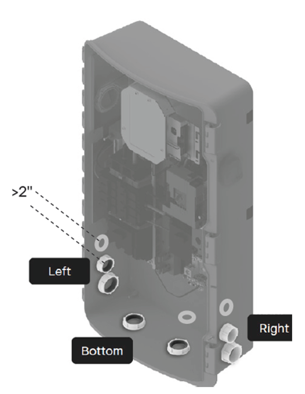
Visit our page on the new IQ8 Microinverter for 3-phase commercial application to learn all about it.
The new IQ8X Microinverter seamlessly integrates with 80 half-cell, 88 half-cell and 96-cell modules with high open circuit voltage (Voc less than 80V) at the lowest temperatures. For a comprehensive overview of its capabilities, refer to the IQ8X Microinverter data sheet available.
Do not parallel or splice battery wires on IQ Battery 3T and 10T terminals. Do not use multi-tap connectors or wire nuts inside the wiring compartment of IQ Battery 3T/10T. Splicing wires on battery terminals or using multi-tap connectors/wire nuts inside the wiring compartments may lead to equipment damage and is a potential fire hazard. The quick install guide (QIG) for IQ Battery 3T/10T, available here, is updated with wiring instructions for paralleling the batteries. You can also refer our training video available here for best practices when wiring IQ Battery 3T and 10T.
We have identified that some IQ System Controller 3/3G units may experience a System Shutdown or Rapid Shutdown state, preventing system provisioning. Our investigations reveal that this issue is due to incorrect factory wiring of the System Shutdown (SSD) switch.
To assist you in resolving this, we have prepared a comprehensive set of wiring tests. These tests are crucial for both the ON and OFF positions of the SSD switch and are designed to guide you through the troubleshooting process with precision and safety.
Detailed instructions are available in our step-by-step guide: How to Fix IQ System Controller Stuck in System Shutdown State.
We highly recommend adhering to all safety protocols outlined in the guide while performing these tests.
Visit our page on the new IQ8 Microinverter for 3-phase commercial application to learn all about it.
The Installer Toolkit App (with the grey icon) has been discontinued. Download the new Enphase Installer App, from the App Store (iOS Devices) or the Play store (Android Devices) to commission new Enphase systems and support the existing ones.
In the Enphase Energy System, meters are also referred to as Current Transformers (CTs). The newly revised Current Transformer health check tech brief contains helpful instructions for conducting a health check for production and consumption meters using the Enphase Installer App or the Enphase Installer Portal.
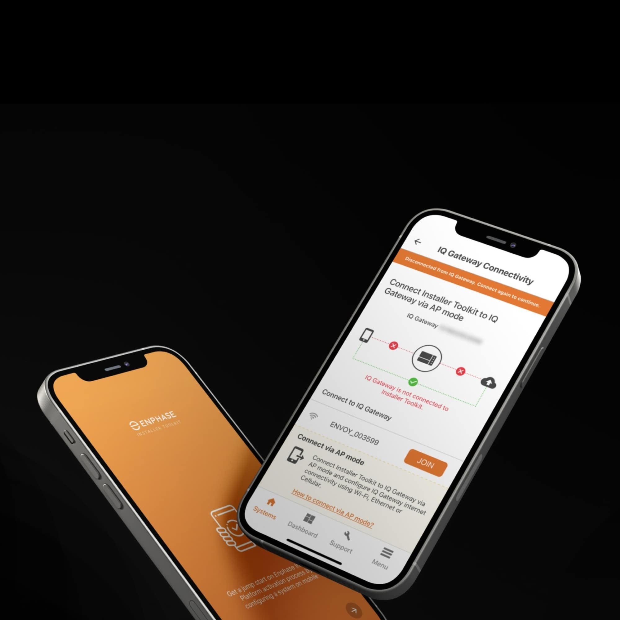
The IQ Gateway is inside the IQ Combiner, and gives a “Gateway not reporting” error in the Enphase App when it is disconnected from the internet and the Enphase Cloud. To address this error, reconnect your IQ Combiner to the Enphase Cloud.
Once connected, wait for the LED indicator next to the cloud icon on the IQ Gateway to turn solid green to confirm successful connection.
SKUs affected.
X2-IQ-AM1-240-4
X2-IQ-AM1-240-4C
X-IQ-AM1-240-5
X-IQ-AM1-240-5C
The Consumption CT (L1, L2) lead wire connection to the IQ Gateway metering ports represented in the wiring label and Quick Install Guide (QIG) for IQ Combiner 4/4C and IQ Combiner 5/5C was incorrect in some production builds. This issue has been rectified in all new units.
How to identify if an IQ Combiner 4/4C or IQ Combiner 5/5C has shipped with the incorrect label?
To identify if an IQ Combiner 4/4C or IQ Combiner 5/5C has been shipped with the incorrect label, check the wiring label (located on the inner door) of your IQ Combiner. If it matches the depiction in Figure A for IQ Combiner 4/4C or Figure B for IQ Combiner 5/5C, your unit has the incorrect wiring label.
Figure A: Incorrect wiring label (Combiner 4/4C)
Figure B: Incorrect wiring label (Combiner5/5C)
The updated, accurate wiring label is shown in Figure C for IQ Combiner 4/4C and Figure D for IQ Combiner 5/5C.
Figure C: Correct wiring label (Combiner 4/4C)
Figure D: Correct wiring label (Combiner 5/5C)
How do you access the corrected Quick Install Guide?
The corrected IQ Combiner 4/4C Quick Install Guide (QIG) and IQ Combiner 5/5C Quick Install Guide (QIG) are now available at the documentation center. Please follow the instructions in the installation guide to ensure the correct installation of the CTs.
What are the corrective actions if the site was already installed incorrectly?
If the CTs were installed incorrectly, the polarity of the readings is reversed. This is generally identified and flagged during commissioning by the Enphase Installer App. However, an incorrect installation can be rectified even after leaving the site using the Reverse Polarity option available in the Enphase Installer Portal.
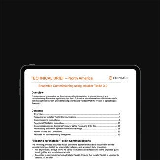
Download the new Storage Troubleshooting Guide 3/3T/10/10T to resolve common issues with the IQ Gateway, IQ System Controller, Communications Kit, IQ Battery, and Current Transformers (CTs).
In this video for installers, the Enphase team gives you a quick tour of the 3rd-generation Enphase Energy System, including the IQ Battery 5P, the IQ System Controller 3/3G, the IQ Combiner 5/5C, and wired control and communications that deliver higher reliability, speed, and performance.
Access the resource centre for various explainer and troubleshooting guides on frequently discussed issues-
How to update homeowner information using the Enphase Installer App
How to troubleshoot powerline noise between the gateway and the microinverters
How to replace an IQ Gateway's serial number for a customer's site using the Enphase Installer App
How to change a systems grid profile using the Enphase Installer App
How to run a grid profile report using the Enphase Installer Portal
How to change the CT polarity using the Enphase Installer Portal
Enphase Service Manager: Managing RMA's and labor reimbursement requests with the Enphase
Enphase Installer Portal: Resending Enphase Account access email to your customer
Enphase Installer Portal: Changing system owner, when no owner present
Enphase Installer Portal: How to add a subcontractor to your company
The new CT installation tech brief includes how CTs work, types of CTs supported by Enphase, recommended installation procedures, and other important details. If any issues arise with CTs in your systems, this video teaches you how to troubleshoot with the Enphase Installer App.
To enhance the mounting stability, we are now including an Anchor Kit with each IQ Battery 5P order. Distributors will provide them, ensuring a hassle-free installation experience. However, in the rare event that the Anchor Kit is not included, you can obtain them for free from the Enphase store, please contact customer support (877)-797-4743, to obtain a coupon code to make it free of charge. We highly recommend using the Anchor Kit during installation to ensure maximum stability. By end of Quarter 3 2023, the Anchor Kit will come pre-installed on the brackets.
To ensure a seamless experience commissioning 3rd-generation Enphase Energy System equipment using the Enphase Installer App, we strongly recommend watching this overview video and making sure you’re using compatible equipment.
Note that an IQ Battery 5P must be installed with an IQ System Controller 3/3G, and cannot be installed with an IQ System Controller or IQ System Controller 2.
An IQ Battery 5P must be installed with an IQ Combiner 5/5C until the Communications Kit 2 becomes available. Orders for the Communications Kit 2 are expected to begin in August.
A unified platform that allows installers to create and manage all their support requests, the Enphase Service Manager can be used to view requests, initiate returns, track return merchandise authorizations, apply for labor reimbursements, and more.
Download the Enphase Service Manager User Guide to learn how to use the platform and make the most of its features on both mobile and desktop.
The new Fleet Management dashboard helps our installer partners and asset owners conveniently manage their fleets and keep track of their performance. Refer to this guide and watch this video to learn more about the dashboard and its features, functions, and capabilities.
Installers can now check real-time microinverter communication and production status through a new validation step in the Enphase Installer App. This is an optional troubleshooting step, and only needs to be performed if any microinverters are facing issues.
For more information, refer to our article on how to use the microinverter validation step.
Download the new Enphase Installer Portal Guide to learn how to access and use the features available in the mobile and desktop view of the Enphase Installer Portal.
When microinverters need to be provisioned and no one is on site to do so, they can be added remotely using the Enphase Installer Portal if the gateway is online and the microinverters are properly wired. Refer to this article for detailed instructions.
These advanced microinverters boast an impressive maximum continuous operating DC current of 14 A. With this enhanced capability, they allow you to incorporate higher current output PV modules into an Enphase Energy System. Additionally, they offer the ability to support 240 V and 208 V single-phase grid services, and deliver greater energy generation at lower DC voltage levels.
For more extensive details, see the data sheets for the IQ8MC, IQ8AC, and IQ8HC.
Download the new Solar Troubleshooting Guide to resolve common IQ Gateway and consumption monitoring issues, including power line noise detection and resolution, IQ Gateway connectivity, CT configuration, and reverse polarity.
Log in to the Enphase Installer Portal and navigate to Devices > Consumption Meter or Production Meter. Select the meter from the list on the Device page, and click Enable or Disable at the bottom of the left pane.
Log in to the Enphase Installer Portal and navigate to Devices > Consumption Meter. Select the meter from the list on the Device page, click the desired option on the left pane under Select Consumption CT Location, and click Change Configuration.
When connected locally to an IQ Gateway, you can reverse CT polarity using the meter wizard in the Enphase Installer App. More details can be found in the Enphase Installer App release notes (3.27.1). The IQ Gateway must be running software version 7.0.104 or greater.
If your company utilizes subcontractors that need access to the Enphase Installer Portal to perform their work, you can now add their existing Enphase Accounts to specific sites in your fleet with limited access. View the “Authorized subcontractor” section in the 22.2.0 release notes for detailed instructions.
Installers can now make sure homeowners have uninterrupted access to their Enphase App. Quickly edit homeowner details on the Enphase Cloud using the Enphase Installer Portal and the Enphase Installer App.
With the updated Enphase Installer Portal, you can send a site-access email to your customers in a few simple steps. This will help you reduce the time it takes to get your customers up, running, and enjoying their new Enphase Energy System. Learn how to resend Enphase access to a homeowner using the Enphase Installer Portal and the Enphase Installer App.
In a few instances, production and consumption meters are inadvertently reversed at commissioning. Learn how to flip the polarity remotely from the Enphase Installer Portal.
You can now issue these tasks remotely:
Provision multiple devices
Force software updates
Reboot IQ Gateways
Check tariffs
Reset IQ Battery devices
You can also perform many more tasks with the new System Diagnostic tool.
This standard isn’t retroactive, and current sites don’t need to make any changes.
These Enphase products have been certified by UL Solutions to UL 1741-SB, 3rd edition to demonstrate compliance with IEEE 1547:2018: IQ7, IQ8, IQ Battery 3/10/3T/10T, and IQ System Controller 1/2. Data sheets have been updated.
New SKUs for IQ Combiner 4/4C (X2-IQ-AM1-240-4, X2-IQ-AM1-240-4C) or IQ Gateway (ENV2-IQ-AM1-240) are needed for IEEE 1547:2018 compliance. See table below. Please confirm with your distributor which SKUs you are scheduled to receive.
Solar Only and most IQ Battery sites will commission as usual with the Enphase Installer App (formerly ITK). For IQ Battery sites with a Zigbee Range Extender, please contact Customer Support to update the IQ Gateway software prior to provisioning the system. This is a temporary step and starting in mid-January this update will be handled by the Enphase Installer App (version 3.28) without the need to contact Customer Support.
| Product | Existing SKU | New SKU (IEEE 1547:2018 |
|---|---|---|
| IQ Combiner 4/4C | X-IQ-AM1-240-4 or X-IQ-AM1-240-4C |
X2-IQ-AM1-240-4 or X2-IQ-AM1-240-4C |
| IQ Gateway | ENV-IQ-AM1-240 | ENV2-IQ-AM1-240 |
Visit the IEEE 1547:2018 explainer page for more information.
Data sheets available in the documentation center.
Select the backup loads so that peak load power consumption does not exceed 30% of AC power rating of the solar system.
Always use one or two IQ Load Controllers and wire them to the essential loads panel and IQ System Controller 2 correctly.
Configure the auxiliary (AUX) contacts in the IQ System Controller 2 using the Enphase Installer App. Failure to do so will result in a dysfunctional Sunlight Backup energy system.
Refer to the support video and technical brief for more details.
As we see more modules entering the market with higher continuous currents, our latest firmware update will be ready to support the increase up to 12A. Read release notes
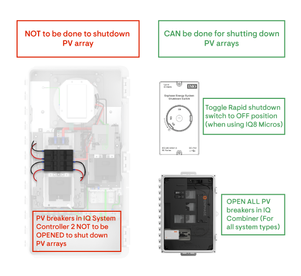
During commissioning or maintenance, DO NOT use the PV breaker in the IQ System Controller 2 to turn off PV. Instead, use either the Rapid Shutdown switch if installed, or use the breakers located in the IQ Combiner box to disconnect the individual PV arrays.
Opening the PV breaker inside of the IQ System Controller 2 will lead to a persistent disconnect state, and the IQ System Controller will never reconnect the PV relay. This is by design to protect appliances and home loads from damage in the event of a breaker failure.
If a PV breaker trips due to an overcurrent event, installers are advised to rectify the fault, close the breakers, and call Enphase Customer Support to remove the error state.
This is applicable for the IQ System Controller 2 installations only.
This release is available for in-progress Enphase Energy System installations using the latest version of the Enphase Installer App and as an over-the-air update for already installed systems. Read the full release notes for more information.
Learn more about the steps to complete a software update:
Before you leave for the install site, open the Enphase Installer App and confirm you are running version 3.27.0. If not, then download the latest update from the Apple App Store or Google Play Store.
In the Installer App settings, check to see if the IQ Gateway has already automatically downloaded version 7.03.120. If not, tap "Download." We recommend performing this step in the office over Wi-Fi prior to going into the field.
Once you arrive on-site, connect to the IQ Gateway and tap "Update Software (v07.03.120)".
The issue with these units has been identified and resolved in our factories and is contained to this specific batch of units.
During commissioning, if you encounter an IQ System Controller 2 that can’t be provisioned and cannot be found during a Bluetooth scan from your mobile device, please contact your Regional Sales Manager or Enphase Customer Support immediately. Press 2-2-2 to quickly route your call to the right support person. We will arrange for our Field Service Team to come on-site and replace the E3 board inside the affected IQ System Controller 2.
Our Customer Service team is available for questions 24/7 and can be reached at 877-797-4743 (707 774-7020 para Español).
Ensure proper grid profile propagation and the ability to disable power production in the IQ Gateway with two short steps:
Update to the latest version of the Enphase Installer App.
Update the IQ Gateway software to version 7.00.92 or later through the Enphase Installer App before provisioning the devices. Software updates can take up to 15-20 minutes.
The existing IQ System Controller 2 SKU EP200G101-M240US01 is being discontinued and replaced by SKU EP200G-SC2-RSD-KIT. The new SKU will include a few additional items:
IQ System Controller 2 (EP200G101-M240US01)
Rapid Shutdown Switch (EP200G-NA-02-RSD)
Circuit breaker (BRK-20A-2P-240V) for powering the IQ Gateway
20ft of color-coded wires and labels for ease of Rapid Shutdown switch wiring
The circuit breaker will be pre-installed in the generator slot in the IQ System Controller 2. For additional information, refer to our commissioning best practices.
Leaving the DC switch ON, without AC power or communication with the IQ Gateway, will drain the battery. Not following these instructions may damage the battery cells and void the limited warranty.
The DC Switch on the IQ Battery must not be turned on before commissioning unless instructed by the Enphase Installer App. Turning the DC switch on before instructed can damage the IQ Battery. After commissioning, always follow the sequence to first supply AC power, and then turn the DC Switch on. The sequence for turning off AC power or DC Switch does not matter.
Learn how to visually inspect a breaker prior to installation.
This practice is very likely to cause an IQ System Controller 2 and IQ Gateway failure. Installers must wire the IQ Gateway breaker in the IQ System Controller. For additional information, refer to the best practices and demonstration video.
The PLC scan will not work if the IQ Gateway version is 5.0.55 or older.
Reverse the polarity of the meters from the Enphase Installer Portal. This will enable you to flip the polarity remotely and ensure correct readings are observed.
Auto-test and self-test aren't enabled for the IQ Gateway in software version 7.0.88. If you are installing an IQ Relay 2.0 with an IQ Gateway running version 7.0.88, please contact Enphase Customer Support to complete the update and generate the self-test report.
Do not wire the Rapid Shutdown switch while the IQ System Controller 2 is energized/powered on. Rapid Shutdown switch installation and wiring should be treated as a live wire installation. De-energize the system when disconnecting and connecting any RSD wiring. For additional information, refer to our commissioning best practices and demonstration video.
Para evitar esta situación, actualice el software del Gateway IQ a través de la aplicación Enphase Installer antes de conectar el Communications Kit al Gateway IQ.
To avoid this, update the IQ Gateway software via the Enphase Installer App prior to connecting the Communications Kit to the IQ Gateway.
Services for your product.
Installation at-home consultation
Need help with installation? Start by booking an At-home Consultation with an independent installation professional to receive a quote for your custom installation.
Confirm your installation zip code:
Please confirm your installation zip code
Are you shipping to your installation address?
Enter your installation address:
Price : $
The At-home Consultation helps determine the full cost to install your new EV charger. The $150 fee is subtracted from your final installation price if you choose to accept the quote. After check out, Enphase will send you an email from its 365 Pronto Platform describing next steps.
Know more
Show less
Frequently bought together

Installation address : , , ,
Installation address : Same as shipping address,
Warning
Installation services are available for a single installation site. If you'd like to get multiple EV chargers installed at different addresses, please complete a separate order for each address. To continue this order, please reduce the charger quantity or remove the install service from your cart.
Store sign in
Please enter your Enphase App credentials.
Back
Forgot your password?
Please enter your email address below to receive a password reset link.